Building The Loader Frame
| How To Series ... Building
A Woodchip Loader (Page #1) Building The Loader Frame |
|
|
|
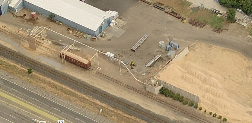
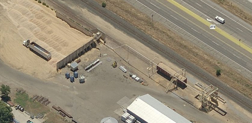
| In this How To series, we will build all of the components
for the entire scene as shown. We will build the Loader Frame, Car Access
Stand with Drop Platform, Woodchip Holding Pen with it's Pump House and
Delivery Plumbing.
This kit is a mixed media kit with Etched & Cast Brass, Styrene Tubing and Laser Cut wood. Although very easy to build, I suggest you read our How To series on Bending Brass if you have never done one of our kits. |
   |
|
|
|
| The main Loader Frame consists of the two Sides and Ends.
Remove these from the kit frets and remove and tie remnants.
There are two different Sides to the frame. The Side with the double X-Bracing be be the side that the Stairs are on. Notice that both Sides have half-etched detail at the X-Bracing center Gussets. |
 |
|
|
|
| Position the Stair Side tabs into the Frame End slots with
the half-etched detail at the X-Bracing center Gussets facing OUTWARD.
Secure the Side to the End.
Now position the other Side tabs into the same Frame End slots with the half-etched detail at the X-Bracing center Gussets facing INWARD. Secure the Side to the End. Secure the other Frame End to the assembly. |
  |
|
|
|
| To build the Stair Support Column, remove the pieces shown
from the kit fret and remove all tie remnants.
Secure the Column Ends on the the Frame with the Support Brackets going through the slots in the Ends. Do both Ends. |
  |
|
|
|
| The Stair Side of the Frame has several small notches the
line-up with notches on the Stair Support Column. Remove the Spacer bars
from the fret and connect the Stair Support Column with the Stair Side by
inserting the top and bottom Spacers in the middle of the Column. Leaving
the slot empty in the center/middle of the column, add the remaining
Spacers
Add the long spacer between the two Frame Sides. This will be the Walkway support. |
  |
|
|
|
| Now add the top Cap Strips to the Frame Sides first, then the Frame Ends and finally on the top of the Stair Column. |   |
|
|
|
| The Staircase has four Stair segments and three Platforms.
Remove the components from the fret and group as shown.
Stairs are built by bending the sides up and pressing on the treads to the correct angle. Bend all Stairs. Platforms have either two or three sides. The Platform sides are bent upwards with the bend-line to the inside of the bend. Bend All Platforms. |
  |
|
|
|
| Add one of the three sided Platforms to the Stair Column. Ensure the Column Side Cap goes into the Tee-Slot in the middle of the Platform. Position the Platform so it is perpendicular to the Column and secure. |  |
|
|
|
| Add an eight tread Stair with the long tabs the middle
three sided stairs on the outside as shown. The bottom of the Stairs has
small tabs that go into slots on the Platform. Once Secure, add the two
sided platform to the assembly. The long tabs on the Stairs are secured to
the underside of the Platform.
Now add the eight tread Stair that has very small tabs. Be sure the tabs are bent inward 90 degrees to the Stair sides. As before, the tabs on the Stair bottom go into slots on the Platform. Secure the top of the Stairs to the Frame Side. |
  |
|
|
|
| Set aside the Frame Assembly and remove the Loading Hood
from the fret. Begin by bending the sides starting with the bend line
closest to the center. This bend will be 90 degrees from the center of the
Hood and you must have the bend on the inside of the bend.
Do both sides.
Bend both ends 90 degrees from the center of the Hood. The ends will be used to help with the last two bends. Now bend the last side bends outward until the flair angle matches the angle of the ends. Site down the length of the hood and ensure all bends are straight. Make adjustments if required. Secure all joints. |
  |
|
|
|
| If you look back at the prototype image, you will notice
that the hood has stiffeners on every panel. Remove the Stiffener Detail
from the fret and remove the end details from the center of the piece.
The Stiffener Detail piece has a section that will correspond to each panel on the Hood. Small little tabs hold each section together, but allow the sections to bend to the same angle of the Hood panels. Carefully align the center of the Stiffener Detail over the center of the Hood so that the ends match up and the gap for bending is at the edges of the Hood center. Secure the Stiffener to the Hood first at the Ends and then around the opening in the center of the Hood. I used a toothpick and small amounts of CA glue to do this. Bend the Detail over the Hood center and into the bend for the flair. Secure the detail into the bend for the Hood flair, then along the bottom and side edges. |
   |
|
|
|
| Using the included rod, cut a piece the width of the Hood. Insert the rod into the holes on the side of the Hood and secure from inside. Cut two 5 inch lengths of the supplied Micro-Chain. Secure the very end of the chain to the rod as shown in the image on one side of the Hood only. Once secure, add the pulley wheel on the rod and secure it. Do the other side of the same Hood end. |  |
|
|
|
| Cut two lengths of the supplied H-Column to 3.0 inches.
Secure them into the openings of the Frame so that they extend from the
Frame 15/16in on the side where the Stairs come up to the top of the Frame
and 9/16in on the other side (no stairs) of the Frame. The opening of the
H-Column should face upwards to accept the chain. Review the images
closely.
Thread the Micro-Chain through the Frame and place it in the groove of the H-Column. Suspend the Hood from the Frame by the Micro-Chain such that the top of the Detail on the Hood is 5/16in below the top of the H-Column when the Hood is level. I used some tape to hold the Chain to the H-Column while adjusting the height of the Hood. Once at the right height, first secure the Chain to the H-Column before securing the other end of the Chain to opposite rod in the Hood Side. |
  |
|
|
|
| The Top Walkway consists of the Grated Walkway and the Railing that has two bends to create a continuous Railing. Secure the railing to the walkway after placing the Railing ends into the appropriate holes in the Walkway. Secure the Walkway to the Frame assembly. |  |
|
|
|
| This concludes the building of the Loader Frame. Here are
two images of the completed assembly.
In the next pages we will build the other components and then build the final scene. |
  |
|
|
|
Note: This document is preliminary. Items contained
within may change without notice. | |